Buick Enclave: Rear Seat Entertainment (RSE) System
The vehicle may have a DVD Rear Seat Entertainment (RSE) system.
The RSE system works with the vehicle's audio system. The DVD player is part of the front radio.
The RSE system includes a radio with a DVD player, a video display screen, audio/video jacks, two wireless headphones, and a remote control. See Operation for more information on the vehicle's infotainment system.
Before Driving
Играй онлайн играть play fortunaThe RSE is designed for rear seat passengers only. The driver cannot safely view the video screen while driving and should not try to do so.
In severe or extreme weather conditions, the RSE system might or might not work until the temperature is within the operating range. The operating range for the RSE system is above −20°C (−4°F) or below 60°C (140°F). If the temperature of the vehicle is outside of this range, heat or cool the vehicle until the temperature is within the operating range of the RSE system.
Parental Control
The RSE system may have a Parental Control feature, depending on the radio.
To enable Parental Control, press and hold the radio power button for more than
two seconds to stop all system features such as: radio, video screen, RSA, DVD and/or
CD. While Parental Control is on,  displays.
When the radio is turned back on, Parental Control is unlocked.
Headphones
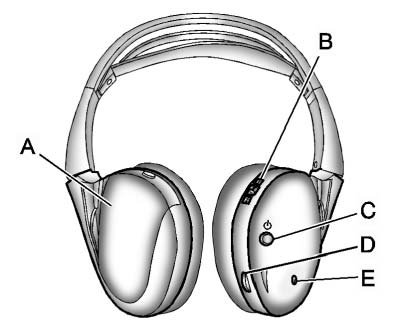
A. Battery cover
B. Channel 1 or 2 switch
C. Power button
D. Volume control
E. Power indicator light
The RSE includes two 2-channel wireless headphones that are dedicated to this system. Channel 1 is dedicated to the video screen, while Channel 2 is dedicated to RSA selections. These headphones are used to listen to media such as CDs, DVDs, MP3/WMAs, DVD-As, radio, any auxiliary source connected to A/V jacks, or the auxiliary input jack, if the vehicle has this feature. The wireless headphones have a power button, channel 1 or 2 switch, and a volume control. Switch the headphones off when not in use.
Push the power button to turn on the headphones. An indicator light located on the headphones comes on. If the light does not come on, the batteries might need to be replaced. Intermittent sound or static on the headphones can also be an indication of weak batteries.
See “Battery Replacement” later in this section for more information.
To adjust the volume on the headphones, use the volume control located on the right side.
Infrared transmitters are located at the rear of the RSE overhead console. The headphones shut off automatically to save the battery power if the RSE system and RSA are shut off or if the headphones are out of range of the transmitters for more than three minutes. Moving too far forward or stepping out of the vehicle, can cause the headphones to lose the audio signa
For optimal audio performance, the headphones must be worn correctly.
Headphones should be worn with the headband over the top of the head for best audio reception.
The symbol L (Left) appears on the outside bottom edge of the ear cup and should be positioned on the left ear. The symbol R (Right) appears on the outside bottom edge of the ear cup and should be positioned on the right ear.
Notice: Do not store the headphones in heat or direct sunlight. This could damage the headphones and repairs will not be covered by the warranty.
Storage in extreme cold can weaken the batteries. Keep the headphones stored in a cool, dry place.
If the foam ear pads attached to the headphones become worn or damaged, the pads can be replaced separately from the headphone set.
To purchase replacement ear pads, call 1-888-293-3332, then prompt zero (0), or contact your dealer.
Headphones should be stored in the front floor console and not in the front seat back pocket. Headphone damage can occur when the second row seats are folded forward.
Battery Replacement
To change the batteries on the headphones:
1. Turn the screw to loosen the battery door located on the left side of the headphones.
Slide the battery door open.
2. Replace the two batteries in the compartment. Make sure that they are installed
correctly, using the diagram on the inside of the battery compartment.
3. Replace the battery door and tighten the door screw.
If the headphones are to be stored for a long period of time, remove the batteries and keep them in a cool, dry place.
Audio/Video (A/V) Jacks
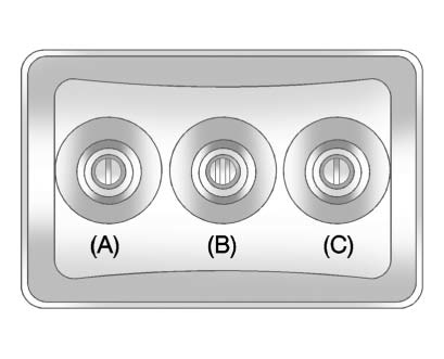
A. Yellow: Video Input
B. White: Left Audio Input
C. Red: Right Audio Input
The A/V jacks are color coded to match typical home entertainment system equipment.
The A/V jacks, located on the rear of the floor console, allow audio or video signals to be connected from an auxiliary device such as a camcorder or a video game unit to the RSE system. Adapter connectors or cables (not supplied) might be required to connect the auxiliary device to the A/V jacks.
Refer to the manufacturer’s instructions for proper usage.
Power for auxiliary devices is not supplied by the radio system.
To use the auxiliary inputs of the RSE system, connect an external auxiliary device to the color-coded A/V jacks and turn both the auxiliary device and the video screen power on. If the video screen is in the DVD player mode, pressing the AUX (auxiliary) button on the remote control switches the video screen from the DVD player mode to the auxiliary device. The radio can listen to the audio of the connected auxiliary device by sourcing to auxiliary. See Auxiliary Devices for more information.
How to Change the RSE Video Screen Settings
The screen display mode (normal, full, and zoom), screen brightness, and setup menu language can be changed from the on screen setup menu by using the remote control.
To change a setting:
1. Press  .
.
2. Use  to navigate and use the setup
menu.
to navigate and use the setup
menu.
3. Press  again to remove the setup
menu from the screen.
again to remove the setup
menu from the screen.
Audio Output
Audio from the DVD player or auxiliary inputs can be heard through the following sources:
► Wireless headphones. Vehicle speakers
. Vehicle-wired headphone jacks on the RSA system, if the vehicle has this feature.
The RSE system always transmits the audio signal to the wireless headphones, if there is audio available. See “Headphones” earlier in this section for more information.
The DVD player is capable of outputting audio to the wired headphone jacks on the RSA system, if the vehicle has this feature. The DVD player can be selected as an audio source on the RSA system. See Rear Seat Audio (RSA) System for more information.
When a device is connected to the A/V jacks, or the radio's auxiliary input jack, if the vehicle has this feature, the rear seat passengers are able to hear audio from the auxiliary device through the wireless or wired headphones. The front seat passengers are able to listen to playback from this device through the vehicle speakers by selecting AUX as the source on the radio.
Video Screen
The video screen is located in the overhead console. When the video screen is not in use, push it up into its locked position.
To use the video screen:
1. Push the release button located on the overhead console.
2. Move the screen to the desired position.
If a DVD is playing and the screen is raised to its locked position, the screen remains on; this is normal, and the DVD continues to play through the previous audio source.
Press  on the remote control or eject
the disc to turn off the screen.
on the remote control or eject
the disc to turn off the screen.
The infrared receivers for the wireless headphones and the remote control are located at the rear of the overhead console.
Notice: Avoid directly touching the video screen, as damage may occur. See “Cleaning the Video Screen” later in this section for more information.
Remote Control
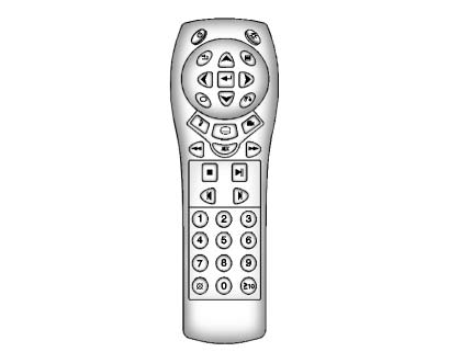
To use the remote control, aim it at the transmitter window at the rear of the overhead console and press the desired button. Direct sunlight or very bright light could affect the ability of the RSE transmitter to receive signals from the remote control. If the remote control does not seem to be working, the batteries might need to be replaced.
See “Battery Replacement” later in this section. Objects blocking the line of sight could also affect the function of the remote control.
If a CD or DVD is in the Radio DVD slot, the remote control
 button can be used to turn on the video
screen display and start the disc.
button can be used to turn on the video
screen display and start the disc.
The radio can also turn on the video screen display. See Operation for more information.
Notice: Storing the remote control in a hot area or in direct sunlight can damage it, and the repairs will not be covered by the warranty. Storage in extreme cold can weaken the batteries. Keep the remote control stored in a cool, dry place.
Remote Control Buttons
 (Power): Press to turn the video
screen on and off.
(Power): Press to turn the video
screen on and off.
 (Illumination): Press to turn the
remote control backlight on.
(Illumination): Press to turn the
remote control backlight on.
The backlight automatically times out after seven to 10 seconds if no other button is pressed while the backlight is on.
 (Title): Press to return the DVD
to the main menu of the DVD. This function could vary for each disc.
(Title): Press to return the DVD
to the main menu of the DVD. This function could vary for each disc.
 (Main Menu): Press to access the
DVD menu. The DVD menu is different on every DVD. Use the navigation arrows to move
the cursor around the DVD menu.
(Main Menu): Press to access the
DVD menu. The DVD menu is different on every DVD. Use the navigation arrows to move
the cursor around the DVD menu.
After making a selection press the enter button. This button only operates when using a DVD.
 (Menu Navigation Arrows):
Use the arrow buttons to navigate through a menu.
(Menu Navigation Arrows):
Use the arrow buttons to navigate through a menu.
 (Enter): Press to select the choice
that is highlighted in any menu.
(Enter): Press to select the choice
that is highlighted in any menu.
 (Display Menu): Press to adjust
the brightness, screen display mode (normal, full, or zoom), and display the language
menu.
(Display Menu): Press to adjust
the brightness, screen display mode (normal, full, or zoom), and display the language
menu.
 (Return): Press to exit the current
active menu and return to the previous menu. This button operates only when the
display menu or a DVD menu is active.
(Return): Press to exit the current
active menu and return to the previous menu. This button operates only when the
display menu or a DVD menu is active.
 (Stop): Press to stop playing, rewinding,
or fast forwarding a DVD. Press twice to return to the beginning of the DVD.
(Stop): Press to stop playing, rewinding,
or fast forwarding a DVD. Press twice to return to the beginning of the DVD.
 (Play/Pause): Press to start playing
a DVD. Press while a DVD is playing to pause it. Press again to continue playing
the DVD.
(Play/Pause): Press to start playing
a DVD. Press while a DVD is playing to pause it. Press again to continue playing
the DVD.
When the DVD is playing, depending on the radio, play may be slowed down by pressing
then
 The DVD continues playing in a slow
play mode.
The DVD continues playing in a slow
play mode.
Depending on the radio, perform reverse slow play by pressing
then
 To cancel slow play mode, press
again.
To cancel slow play mode, press
again.
 (Previous Track/Chapter):
Press to return to the start of the current track or chapter. Press again to go to the previous track or chapter. This button might not work when the DVD is playing the copyright information or the previews.
 (Next Track/Chapter): Press to go
to the beginning of the next chapter or track. This button might not work when the
DVD is playing the copyright information or the previews.
(Next Track/Chapter): Press to go
to the beginning of the next chapter or track. This button might not work when the
DVD is playing the copyright information or the previews.
(Fast Reverse): Press to quickly
reverse the DVD or CD.
To stop fast reversing a DVD video, press
To stop fast reversing a DVD audio
or CD, release This button might not
work when the DVD is playing the copyright information or the previews.
(Fast Forward): Press to fast forward
the DVD or CD. To stop fast forwarding a DVD video, press
or CD, release
. This button might not work when the
DVD is playing the copyright information or the previews.
 (Audio): Press to change audio tracks
on DVDs that have this feature when the DVD is playing.
(Audio): Press to change audio tracks
on DVDs that have this feature when the DVD is playing.
The format and content of this function vary for each disc.
 (Subtitles): Press to turn ON/OFF
subtitles and to move through subtitle options when a DVD is playing. The format
and content of this function vary for each disc.
(Subtitles): Press to turn ON/OFF
subtitles and to move through subtitle options when a DVD is playing. The format
and content of this function vary for each disc.
AUX (Auxiliary): Press to switch the system between the DVD player and an auxiliary source.
 Camera): Press to change camera
angles on DVDs that have this feature when a DVD is playing.
Camera): Press to change camera
angles on DVDs that have this feature when a DVD is playing.
The format and content of this function vary for each disc.
► through 0 (Numeric Keypad):The numeric keypad provides the capability of direct chapter or track number selection.
 (Clear): Press within three seconds
after entering a numeric selection, to clear all numerical inputs.
(Clear): Press within three seconds
after entering a numeric selection, to clear all numerical inputs.
 10 (Double Digit Entries): Press
to select chapter or track numbers greater than nine. Press this button before entering
the number.
10 (Double Digit Entries): Press
to select chapter or track numbers greater than nine. Press this button before entering
the number.
If the remote control becomes lost or damaged, a new universal remote control can be purchased.
If this happens, make sure the universal remote control uses a Toshiba® code set.
Battery Replacement
To change the remote control batteries:
1. Slide the rear cover back on the remote control.
2. Replace the two batteries in the compartment. Make sure that they are installed
correctly, using the diagram on the inside of the battery compartment.
3. Replace the battery cover.
If the remote control is to be stored for a long period of time, remove the batteries and keep them in a cool, dry place.
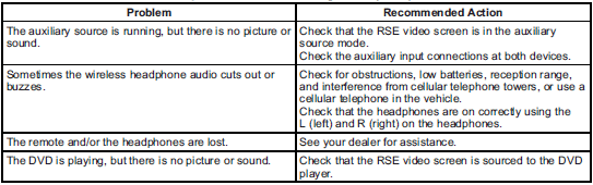
Tips and Troubleshooting Chart
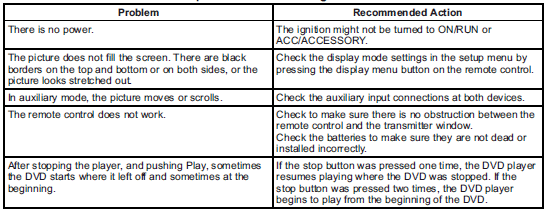
Tips and Troubleshooting Chart (cont.)
DVD Display Error Messages
The DVD display error message depends on which radio the vehicle has. The video screen might display one of the following:
Disc Load/Eject Error: This message displays when there are disc load or eject problems.
Disc Format Error: This message displays if the disc is inserted with the disc label wrong side up, or if the disc is damaged.
Disc Region Error: This message displays if the disc is not from a correct region.
No Disc Inserted: This message displays if no disc is present when the
 EJECT button is pressed on the radio.
DVD Distortion
Video distortion can occur when operating cellular phones, scanners, CB radios, Global Position Systems (GPS)*, two-way radios, mobile faxes, or walkie talkies.
It might be necessary to turn off the DVD player when operating one of these devices in or near the vehicle.
*Excludes the OnStar® System.
Cleaning the RSE Overhead Console
When cleaning the RSE overhead console surface, use only a clean cloth dampened with clean water.
Cleaning the Video Screen
Use only a clean cloth dampened with clean water. Use care when directly touching or cleaning the screen, as damage could result.

