Buick Enclave: Repair Instructions
ALUMINUM WHEEL POROSITY REPAIR
1. Remove the tire and wheel. Refer to Tire and Wheel Removal and Installation.
2. Inflate the tire to the manufactures specified pressure as stated on the tire.
3. Submerge the tire/wheel into a water bath in order to locate the leak.
4. Inscribe a mark on the wheel in order to indicate the leak areas.
5. Inscribe a mark on the tire at the valve stem in order to Indicate the orientation of the tire to the wheel.
6. Remove the tire from the wheel. Refer to Tire Dismounting and Mounting.
7. Use number 80 grit sandpaper to scuff the inside of the rim surface at the leak area.
IMPORTANT: Do not damage the exterior surface of the wheel.
8. Use general purpose cleaner such as 3M, P/N 08984 or equivalent, to clean the leak area.
9. Apply 3 mm (0.12 in) thick layer of adhesive/sealant, GM P/N 12378478, (Canadian P/N 88900041) or equivalent to the leak area.
10. Allow for the adhesive/sealant to dry.
11. Align the inscribed mark on the tire with the valve stem on the wheel.
12. Install the tire to the wheel. Refer to Tire Dismounting and Mounting.
13. Inflate the tire to the manufactures specified pressure as stated on the tire.
14. Submerge the tire/wheel into a water bath in order to ensure the leak is sealed.
15. Balance the tire and wheel. Refer to Tire and Wheel Assembly Balancing - Off Vehicle.
16. Install the tire and wheel. Refer to Tire and Wheel Removal and Installation.
17. Lower the vehicle.
ALUMINUM WHEEL REFINISHING
Finish Damage Evaluation Procedure
1. Inspect the wheels for damage from uncoated wheel balance weights or from automatic car wash facilities.
NOTE:
- If the wheels are chrome-plated, do not re-plate or refinish the wheels.
- If the wheels are polished aluminum, do not refinish the wheels in the dealer environment. Utilize a refinisher that meets manufacturer guidelines.
2. Inspect the wheels for the following conditions:
- Corrosion
- Scrapes
- Gouges
3. Verify the damage is not deeper than what sanding can remove.
4. Inspect the wheels for cracks. If a wheel has cracks, discard the wheel.
5. Inspect the wheels for bent rim flanges. If a rim flange is bent, discard the wheel.
Refinishing Procedure
1. Remove the tire and wheel assembly from the vehicle. Refer to Tire and Wheel Removal and Installation.
WARNING: To avoid serious personal injury when applying any two part component paint system, follow the specific precautions provided by the paint manufacturer. Failure to follow these precautions may cause lung irritation and allergic respiratory reaction.
2. Remove the balance weights from the wheel.
3. Remove the tire from the wheel. Refer to Tire Dismounting and Mounting.
4. Use a suitable cleaner in order to remove the following contaminants from the wheel:
- Lubricants
- Wax
- Dirt
5. Use plastic media blasting in order to remove the paint from the wheel.
NOTE:
- Do not re-machine the wheel.
- Do not use chemicals in order to strip the paint from the wheel.
6. If the wheel had a machined aluminum finish, spin the wheel and use sand paper in order to restore the circular machined appearance.
7. Mask the wheel mounting surface and the wheel nut contact surface.
NOTE: The wheel mounting surface and the wheel nut contact surface must remain free of paint.
8. Follow the paint manufacturer's instructions for painting the wheel.
9. Unmask the wheel.
10. Install a new valve stem.
11. Install the tire to the wheel. Refer to Tire Dismounting and Mounting.
NOTE: Use new coated balance weights in order to balance the wheel.
12. Use a suitable cleaner in order to remove the following contaminants from the wheel mounting surface:
- Corrosion
- Overspray
- Dirt
13. Install the tire and wheel assembly to the vehicle. Refer to Tire and Wheel Removal and Installation.
TIRE AND WHEEL REMOVAL AND INSTALLATION
Special Tools
- CH-41013 Rotor Resurfacing Kit
- CH-42450-A Wheel Hub Resurfacing Kit
For equivalent regional tools, refer to Special Tools.
Removal Procedure
1. Raise and support the vehicle. Refer to Lifting and Jacking the Vehicle.
2. Remove the wheel center cap, if equipped.
3. Remove the wheel nut caps (1), if equipped.
Fig. 6: Wheel Nut Caps
4. Remove the wheel nuts (1).
Fig. 7: Wheel Nuts
5. Remove the tire and wheel assembly (1).
Fig. 8: Tire And Wheel Assembly
6. If the tire and wheel assembly is difficult to remove or cannot be removed, perform the following steps:
WARNING: If penetrating oil gets on the vertical surfaces between the wheel and the rotor or drum it could cause the wheel to work loose as the vehicle is driven, resulting in loss of control and an injury accident.
CAUTION: Removing the wheel may be difficult because of foreign materials or a tight fit between the wheel and the hub/rotor. Slightly tap the tire side wall with a rubber mallet in order to remove the wheel. Failure to follow these instructions may result in damage to the wheel.
CAUTION: Never use heat to loosen a tight wheel bolt or nut. This can shorten the life of wheel and damage wheel bearings.
- Hand install the wheel nuts.
- Loosen the wheel nuts 2 complete turns.
- Lower the vehicle.
- Rock the vehicle from side to side.
- Repeat the procedure if necessary.
7. When the tire and wheel assembly loosens, raise and support the vehicle. Refer to Lifting and Jacking the Vehicle.
8. Remove the wheel nuts.
9. Remove the tire and wheel assembly.
Installation Procedure
1. Using a wire brush or wire wheel, clean the wheel to brake rotor or drum mating surface.
WARNING: Before installing the wheels, remove any buildup of corrosion on the wheel mounting surface and brake drum or disc mounting surface.
Installing wheels with poor metal-to-metal contact at the mounting surfaces can cause wheel nuts to loosen. This can cause a wheel to come off when the vehicle is moving, causing loss of control and possibly personal injury.
NOTE: Do not use power grinding tools to clean the brake rotor or drum to wheel mating surfaces.
2. Using the CH-41013 Rotor Resurfacing Kit, clean the rotor or drum to wheel contact area.
3. Using the CH-42450-A Wheel Hub Resurfacing Kit, clean the surfaces around the wheel studs.
4. Clean the threads of the wheel studs.
5. If the threads of the wheel stud are damaged, replace the wheel stud. Refer to Wheel Stud Replacement or Wheel Stud Replacement.
6. After cleaning all of the wheel and brake rotor or drum contact areas, use brake cleaner or denatured alcohol to remove any dirt and debris from the wheel nuts and the brake rotor or drum.
7. Inspect and clean the contact areas of the wheel. Refer to Wheel Mounting Surface Check.
8. Apply a small amount of lubricant to the inner diameter of the wheel hub pilot hole (1) where it contacts the wheel hub flange. Refer to Adhesives, Fluids, Lubricants and Sealers.
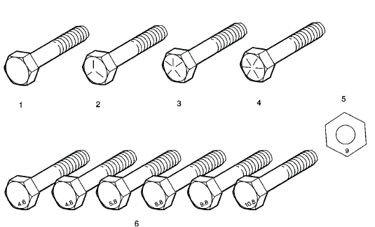
Fig. 9: Rim Inner Center Seat
9. Install the tire and wheel assembly (1).
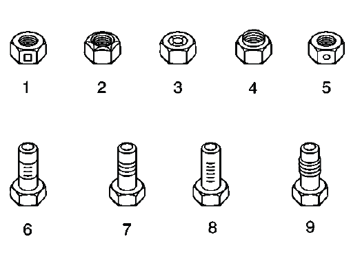
Fig. 10: Tire And Wheel Assembly
10. Hand install the wheel nuts (1).
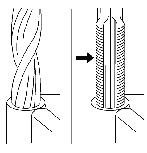
Fig. 11: Wheel Nuts
WARNING: Never grease or lubricate wheel nuts, studs and mounting surfaces.
Wheel nuts, studs and mounting surfaces must be clean and dry.
Tightening the lubricated parts can cause damage to the wheel studs. This can cause a wheel to come off when the vehicle is moving, causing loss of control and possibly personal injury.
11. Using a torque wrench and the appropriate socket, alternately and evenly tighten the wheel nuts to 190 (140 lb ft) in the sequence illustrated.
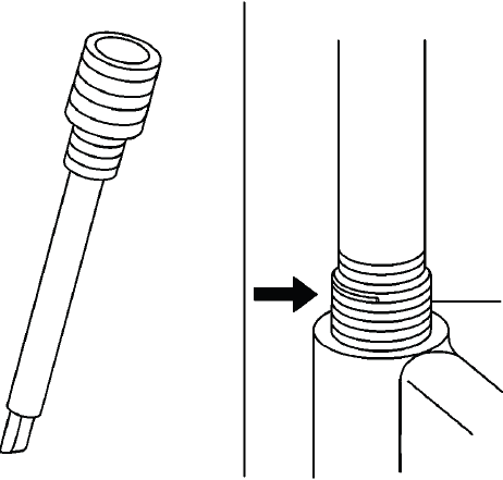
Fig. 12: Wheel Nut Tightening Sequence
CAUTION: Improperly tightened wheel bolts or nuts can lead to brake pulsation and rotor damage. In order to avoid expensive brake repairs, evenly tighten the wheel bolts or nuts to the proper torque specification.
CAUTION: Refer to Fastener Caution.
12. Install the wheel nut caps (1), if equipped.
Fig. 13: Wheel Nut Caps
13. Install the wheel center cap, if equipped.
TIRE REPAIR
Many different materials and techniques are available on the market in order to repair tires. Not all of the materials and techniques work on some types of tires. Tire manufacturers have published detailed instructions on how and when to repair tires. Obtain the instructions from the manufacturer. Do NOT repair the compact spare tire.
TIRE DISMOUNTING AND MOUNTING
CAUTION: Use a tire changing machine in order to dismount tires. Do not use hand tools or tire irons alone in order to remove the tire from the wheel. Damage to the tire beads or the wheel rim could result.
CAUTION: Do not scratch or damage the clear coating on aluminum wheels with the tire changing equipment. Scratching the clear coating could cause the aluminum wheel to corrode and the clear coating to peel from the wheel.
1. Remove the valve core from the valve stem.
CAUTION: Damage to either the tire bead or the wheel mounting holes can result from the use of improper wheel attachment or tire mounting procedures. It takes up to 70 seconds for all of the air to completely exhaust from a large tire. Failure to follow the proper procedures could cause the tire changer to put enough force on the tire to bend the wheel at the mounting surface. Such damage may result in vibration and/or shimmy and under severe usage lead to wheel cracking.
2. Deflate the tire completely.
3. Use the tire changer in order to remove the tire from the wheel. Follow steps 4-7 to remove the tire from the wheel.
NOTE: Rim-clamp European-type tire changers are recommended.
4. When separating the tire bead from the wheel, position the bead breaking fixture 90, 180 and 270 degrees from the valve stem.
Fig. 14: Using Tire Changer to Remove Tire
5. Position the wheel and tire so the valve stem is at the 7 o'clock position relative to the head. Apply tire bead lubricant to the pry bar to prevent damage to the tire bead. The tire iron or pry bar can be inserted when prying the outer tire bead up and over the mounting/dismounting head.
CAUTION: Failure to position valve stem in proper position while dismounting and mounting the tire may result in the TPM sensor to become damaged.
6. Position the wheel and tire so the valve stem is again at the 7 o'clock position relative to the head. The tire iron or pry bar can be inserted when prying the inner tire bead up and over the mounting/dismounting head.
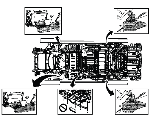
Fig. 15: Separating Tire Bead from Wheel
7. Remove all residual liquid sealant from the inside of the tire and wheel surfaces. If any tire sealant is noted upon tire dismounting on vehicles equipped with TPM, replace the tire pressure sensor. Refer to Tire Pressure Indicator Sensor Replacement (Snap In Style).
8. Use medium coarseness steel wool in order to remove any rubber, light rust or corrosion from the wheel bead seats.
9. Apply mounting lubricant to the tire bead and the wheel rim. Refer to Adhesives, Fluids, Lubricants and Sealers.
CAUTION: When mounting the tires, use an approved tire mounting lubricant.
DO NOT use silicon or corrosive base compounds to lubricate the tire bead and the wheel rim. A silicon base compound can cause the tire to slip on the rim. A corrosive type compound can cause tire or rim deterioration.
10. Position the rim so the valve stem (1) is at the 7 o'clock position relative to the head (2). This will protect the sensor when the bottom bead seats.
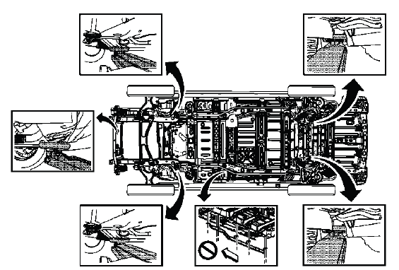
Fig. 16: Position Rim So Valve Stem Is At 7 O'clock Position Relative To Head
11. Using the tire machine, rotate the tire/wheel assembly clockwise when transferring the tire bead to the inside of the wheel rim. Ensure that the valve stem (1) is at the 7 o'clock position.
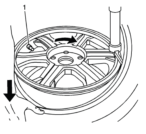
Fig. 17: Ensure Valve Stem Is At 7 O'clock Position
12. After the bottom bead is on the wheel, reposition the wheel and tire so that the valve stem (1) is at the 7 o'clock position relative to the head. This will protect the sensor while mounting the tire bead to the outside of the wheel.
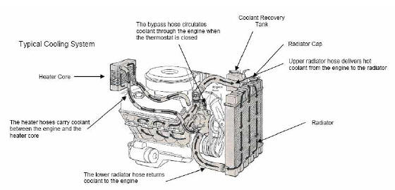
Fig. 18: Reposition Wheel And Tire So Valve Stem Is At 7 O'clock Position
Relative To Head
13. Use the tire changer in order to install the tire to the wheel.
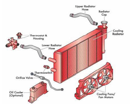
Fig. 19: Transferring Tire Bead
14. Inflate the tire until it passes the bead humps. Be sure that the valve core is not installed at this time.
WARNING: To avoid serious personal injury, do not stand over tire when inflating. The bead may break when the bead snaps over the safety hump. Do not exceed 275 kPa (40 psi) pressure when inflating any tire if beads are not seated. If 275 kPa (40 psi) pressure will not seat the beads, deflate, relubricate the beads and reinflate. Overinflation may cause the bead to break and cause serious personal injury.
15. Install the valve core to the valve core stem.
16. Inflate the tire to the proper air pressure.
17. Ensure that the locating rings are visible on both sides of the tire in order to verify that the tire bead is fully seated on the wheel.
TIRE ROTATION
Rotate the tires and wheels at frequent intervals to equalize wear. In addition to scheduled rotation, rotate the tire and wheel whenever uneven tire wear is noticed.
Radial tires tend to wear faster in the shoulder area, particularly in front positions. Radial tires in non-drive locations may develop an irregular wear pattern that may increase tire noise. This makes regular rotation especially necessary.
Refer to Tire and Wheel Removal and Installation for tire removal.
Fig. 20: Identifying Tire Rotation Pattern
Always use a 4-wheel rotation. After rotation, check the wheel nuts for specified torque. Then, set the tire pressure.
SPARE WHEEL HOIST REPLACEMENT

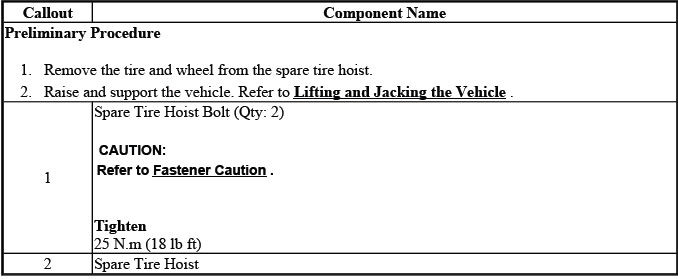
Fig. 21: Identifying Spare Wheel Hoist
Spare Wheel Hoist Replacement
