Buick Enclave: Repair Instructions
FRONT DISC BRAKE PADS REPLACEMENT
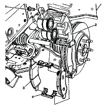
Fig. 12: View Of Front Disc Brake Pads
Front Disc Brake Pads Replacement

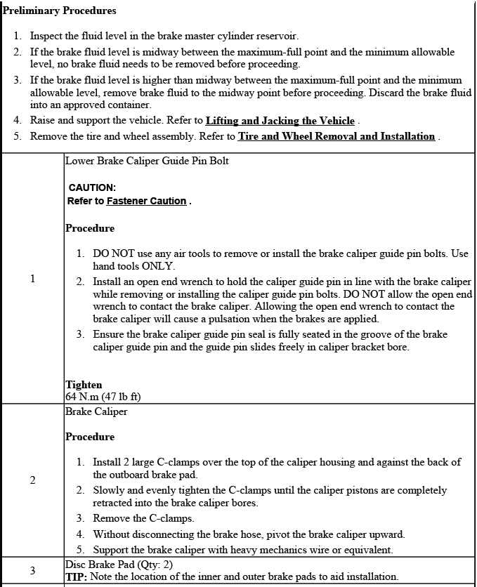
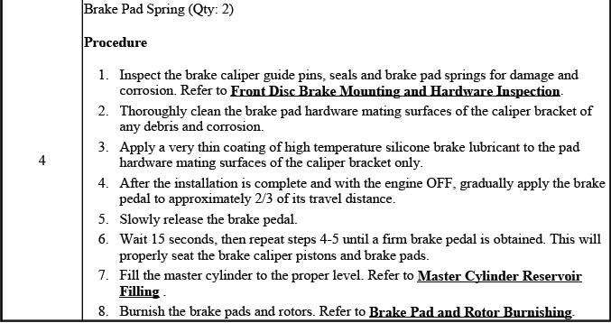
REAR DISC BRAKE PADS REPLACEMENT
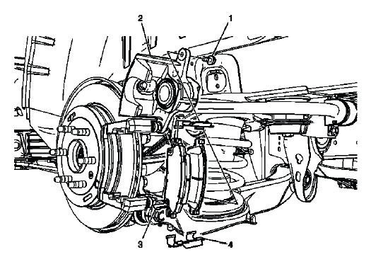
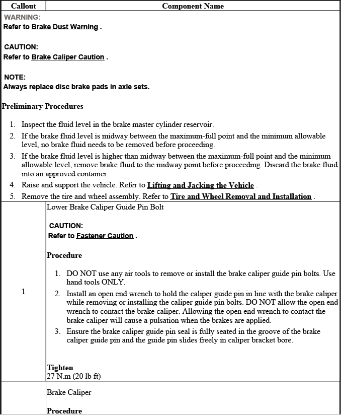
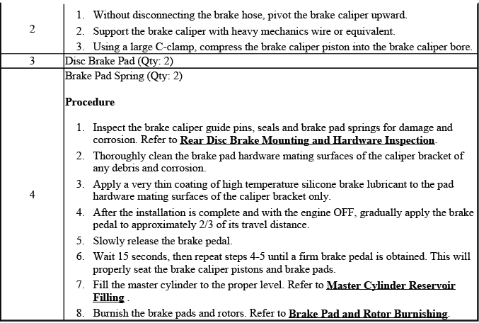
Fig. 13: Identifying Rear Disc Brake Pads
Rear Disc Brake Pads Replacement
BRAKE PAD AND ROTOR BURNISHING
WARNING: Road test a vehicle under safe conditions and while obeying all traffic laws. Do not attempt any maneuvers that could jeopardize vehicle control.
Failure to adhere to these precautions could lead to serious personal injury and vehicle damage.
Burnishing the brake pads and brake rotors is necessary in order to ensure that the braking surfaces are properly prepared after service has been performed on the disc brake system.
This procedure should be performed whenever the disc brake rotors have been refinished or replaced, and/or whenever the disc brake pads have been replaced.
1. Select a smooth road with little or no traffic.
2. Accelerate the vehicle to 48 km/h (30 mph).
NOTE: Use care to avoid overheating the brakes while performing this step.
3. Using moderate to firm pressure, apply the brakes to bring the vehicle to a stop. Do not allow the brakes to lock.
4. Repeat steps 2 and 3 until approximately 20 stops have been completed. Allow sufficient cooling periods between stops in order to properly burnish the brake pads and rotors.
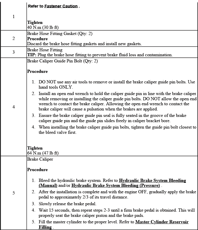
FRONT BRAKE CALIPER REPLACEMENT
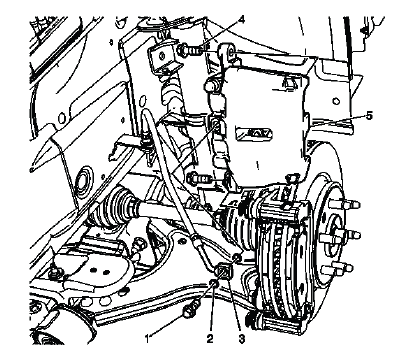
Fig. 14: View Of Front Brake Caliper
Front Brake Caliper Replacement
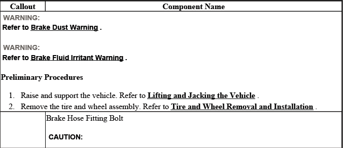
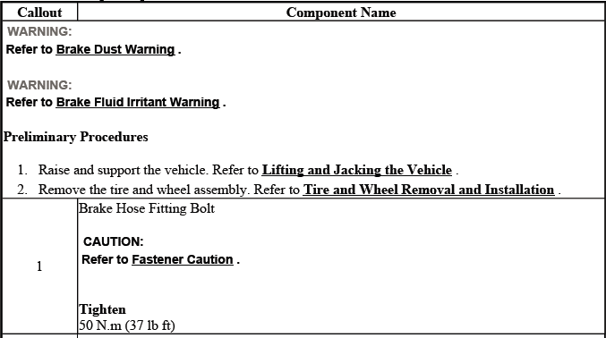
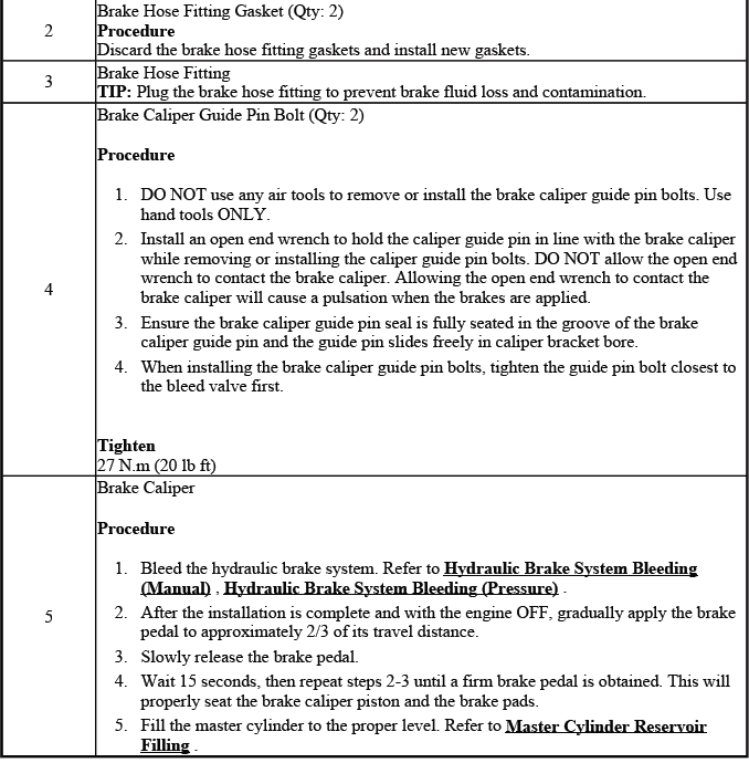
REAR BRAKE CALIPER REPLACEMENT
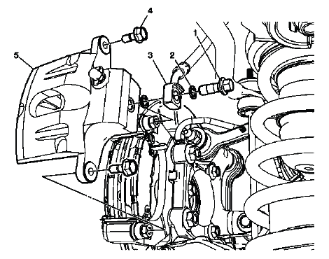
Fig. 15: Identifying Rear Brake Caliper
Rear Brake Caliper Replacement
FRONT BRAKE CALIPER HARDWARE REPLACEMENT
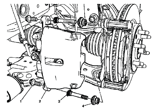
Fig. 16: Identifying Front Disc Brake Hardware
Front Brake Caliper Hardware Replacement
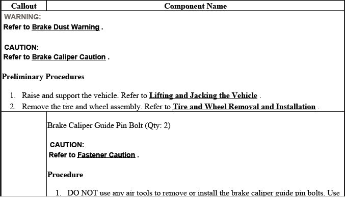
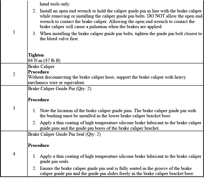
REAR BRAKE CALIPER HARDWARE REPLACEMENT
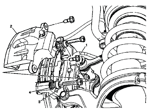
Fig. 17: View Of Rear Disc Brake Hardware
Rear Brake Caliper Hardware Replacement
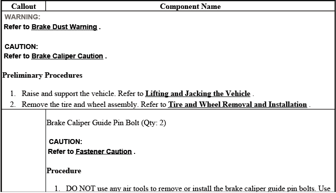
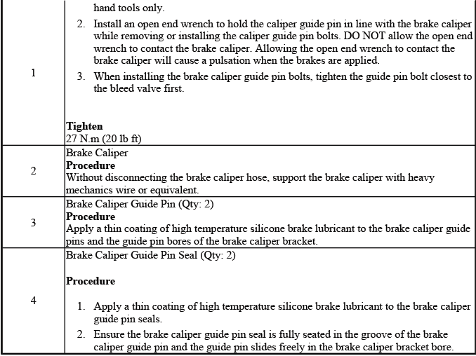
FRONT BRAKE CALIPER BRACKET REPLACEMENT
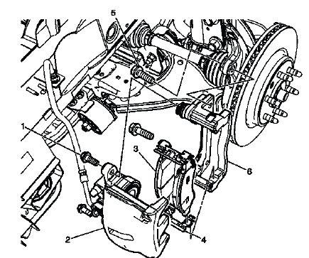
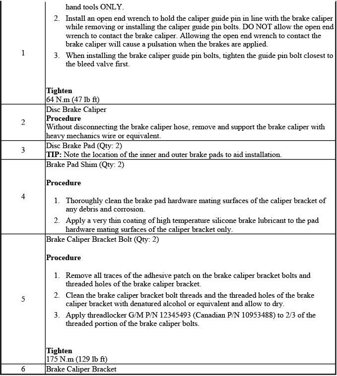
Fig. 18: View Of Front Brake Caliper Bracket
Front Brake Caliper Bracket Replacement
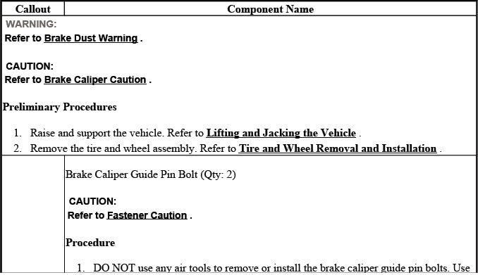
REAR BRAKE CALIPER BRACKET REPLACEMENT
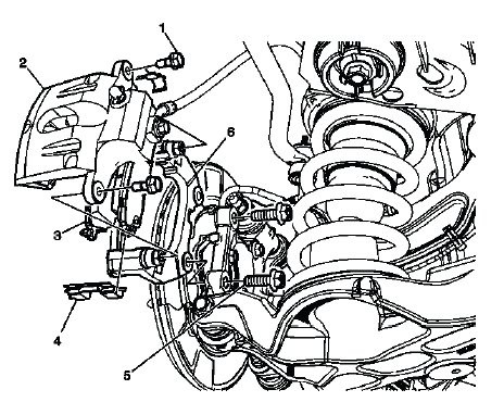
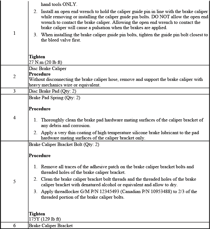
Fig. 19: View Of Rear Brake Caliper Bracket
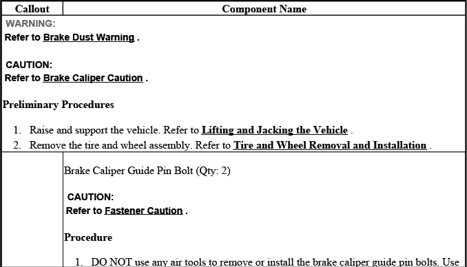
Rear Brake Caliper Bracket Replacement
FRONT BRAKE ROTOR REPLACEMENT
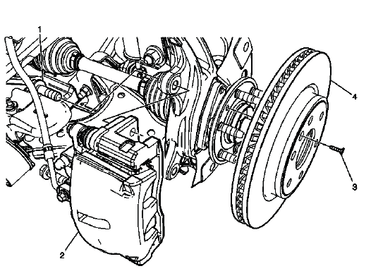
Fig. 20: View Of Front Brake Rotor
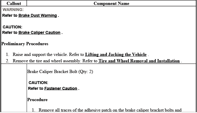
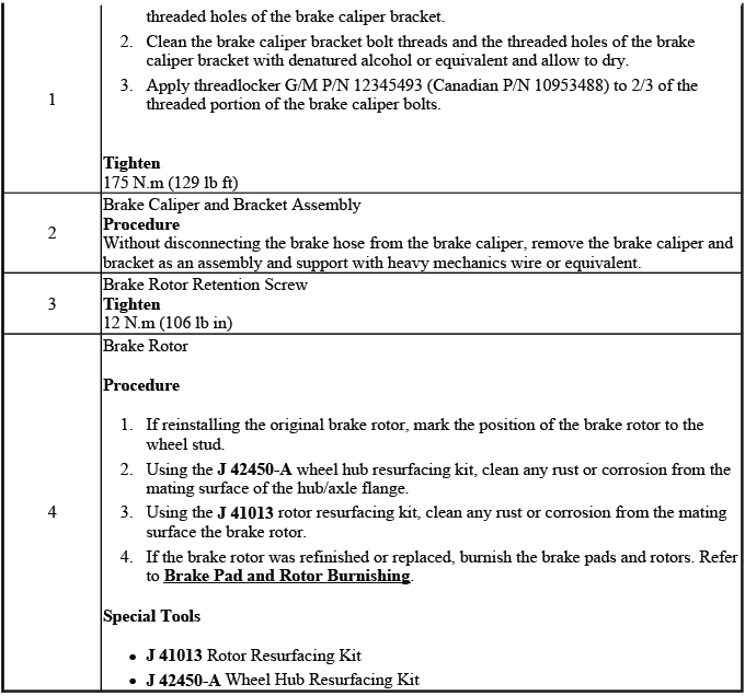
Front Brake Rotor Replacement
REAR BRAKE ROTOR REPLACEMENT
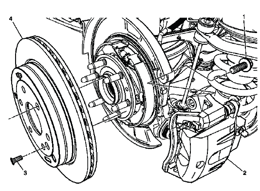
Fig. 21: Identifying Rear Brake Rotor
Rear Brake Rotor Replacement
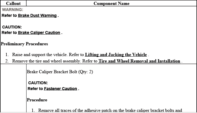
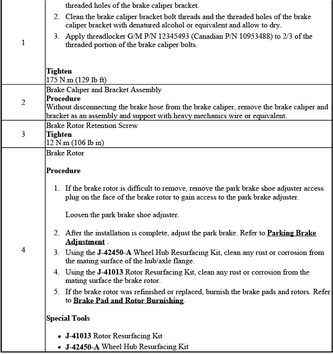
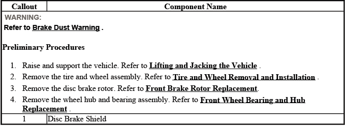
FRONT BRAKE SHIELD REPLACEMENT
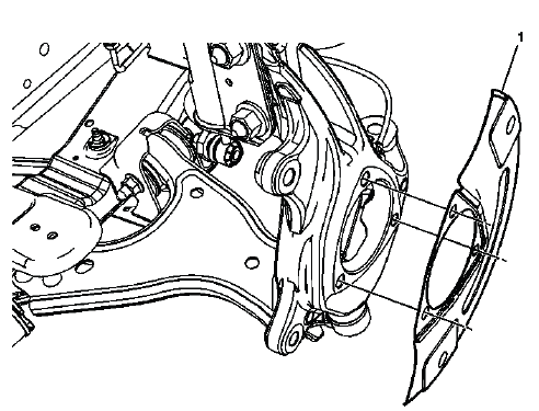
Fig. 22: View Of Front Brake Shield
Front Brake Shield Replacement
BRAKE ROTOR ASSEMBLED LATERAL RUNOUT CORRECTION
NOTE:
- Brake rotor thickness variation MUST be checked BEFORE checking for assembled lateral runout (LRO). Thickness variation exceeding the maximum acceptable level can cause brake pulsation. Refer to Brake Rotor Thickness Variation Measurement.
- Brake rotor assembled lateral runout (LRO) exceeding the maximum
allowable specification can cause thickness variation to develop in the
brake rotor over time, usually between 4, 800-11, 300 km (3, 000-7, 000 mi).
Refer to Brake Rotor Assembled Lateral Runout Measurement.
Review the following acceptable methods for bringing the brake rotor assembled LRO to within specifications.
Determine which method to use for the specific vehicle being repaired.
- The indexing method of correcting assembled LRO is most effective when the LRO specification is only exceeded by a relatively small amount: 0.025-0.127 mm (0.001-0.005 in). Indexing is used to achieve the best possible match of high spots to low spots between related components. Refer to Brake Rotor Assembled Lateral Runout Correction - Indexing.
- The correction plate method of correcting assembled LRO involves the addition of a tapered plate between the brake rotor and the hub/axle flange. The correction plate method can be used to correct LRO that exceeds the specification by up to 0.23 mm (0.009 in). Refer to Brake Rotor Assembled Lateral Runout Correction - Correction Plates.
- The on-vehicle brake lathe method is used to bring the LRO to within specifications through compensating for LRO while refinishing the brake rotor. Refer to Brake Rotor Assembled Lateral Runout Correction - On Vehicle Lathe.
If the assembled LRO cannot be corrected using these methods, then other components must be suspected as causing and/or contributing to the LRO concern.
BRAKE ROTOR ASSEMBLED LATERAL RUNOUT CORRECTION - INDEXING
NOTE: This Procedure is not used in Europe
Special Tools
- CH-45101-100 Conical Brake Rotor Washers
For equivalent regional tools, refer to Special Tools.
1. Remove the CH-45101-100 Conical Brake Rotor Washers and the lug nuts that were installed during the assembled LRO measurement procedure.
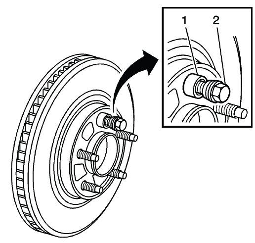
Fig. 23: Identifying Special Tool J 45101-100 & Lug Nut
WARNING: Refer to Brake Dust Warning.
NOTE: Brake rotor thickness variation MUST be checked BEFORE checking for assembled lateral runout (LRO). Thickness variation exceeding the maximum acceptable level can cause brake pulsation. Refer to Brake Rotor Thickness Variation Measurement.
Brake rotor assembled LRO exceeding the maximum allowable specification can cause thickness variation to develop in the brake rotor over time, usually between 4, 800-11, 300 km (3, 000-7, 000 mi).
Refer to Brake Rotor Assembled Lateral Runout Measurement.
2. Inspect the mating surface of the hub/axle flange and the brake rotor to ensure that there are no foreign particles or debris remaining.
3. Index the brake rotor in a different orientation to the hub/axle flange.
4. Hold the rotor firmly in place against the hub/axle flange and install one of the CH-45101-100 Conical Brake Rotor Washers (1) and one lug nut (2) onto the upper-most wheel stud.
5. Continue to hold the rotor secure and tighten the lug nut firmly by hand.
6. Install the remaining CH-45101-100 Conical Brake Rotor Washers and lug nuts onto the wheel studs and tighten the nuts firmly by hand in a star-pattern.
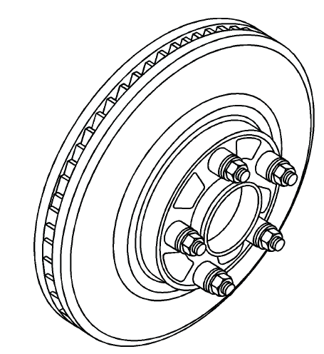
Fig. 24: Identifying All Special Tools J 45101-100s & Lug Nuts
7. Tighten the lug nuts in a star-pattern to specification, in order to properly secure the rotor. Refer to Tire and Wheel Removal and Installation.
8. Measure the assembled LRO of the brake rotor. Refer to Brake Rotor Assembled Lateral Runout Measurement.
9. Compare the amount of change between this measurement and the original measurement.
10. If this measurement is within specifications, proceed to step 14.
11. If this measurement still exceeds specifications, repeat steps 1-9 until the best assembled LRO measurement is obtained.
12. Matchmark the final location of the rotor to the wheel studs if the orientation is different than it was originally.
13. If the brake rotor assembled LRO measurement still exceeds the maximum allowable specification, refer to Brake Rotor Assembled Lateral Runout Correction.
14. If the brake rotor assembled LRO is within specification, install the brake caliper and depress the brake pedal several times to secure the rotor in place before removing the CH-45101-100 Conical Brake Rotor Washers and the lug nuts.
BRAKE ROTOR ASSEMBLED LATERAL RUNOUT CORRECTION - CORRECTION PLATES
NOTE: This procedure not used in Europe
Special Tools
- CH-45101-100 Conical Brake Rotor Washers
For equivalent regional tools, refer to Special Tools.
1. Rotate the brake rotor to position the high spot, identified and marked during the brake rotor assembled LRO measurement procedure, to face upward.
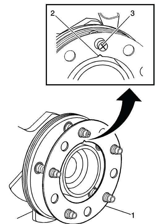
Fig. 25: Identifying Correction Plate, High Spot Mark & V-Shaped Notch
WARNING: Refer to Brake Dust Warning.
NOTE:
- Brake rotor thickness variation MUST be checked BEFORE checking for assembled lateral runout (LRO). Thickness variation exceeding the maximum acceptable level can cause brake pulsation. Refer to Brake Rotor Thickness Variation Measurement.
- Brake rotor assembled LRO exceeding the maximum allowable
specification can cause thickness variation to develop in the brake
rotor over time, usually between 4, 800-11, 300 km (3, 000-7, 000 mi).
Refer to Brake Rotor Assembled Lateral Runout Measurement.
2. Remove the CH-45101-100 Conical Brake Rotor Washers and the lug nuts that were installed during the assembled LRO measurement procedure and/or the indexing correction procedure.
3. Inspect the mounting surface of the hub/axle flange and the brake rotor to ensure that there are no foreign particles or debris remaining.
4. Select the correction plate, following the manufacturer's instructions, which has a specification closest to the assembled LRO measurement.
For example: If the assembled LRO measurement was 0.076 mm (0.003 in), the 0.076 mm (0.003 in) correction plate would be used. If the measurement was 0.127 mm (0.005 in), the 0.152 mm (0.006 in) correction plate would be used.
5. Determine the positioning for the correction plate (1) using the high spot mark (3) made during the brake rotor assembled LRO measurement procedure.
6. Install the correction plate (1) onto the hub/axle flange, with the V-shaped notch (2) orientated to align with the high spot mark (3), that was positioned to face upward.
NOTE:
- Do NOT install used correction plates in an attempt to correct brake rotor assembled LRO.
- Do NOT stack up or install more than one correction plate onto one hub/axle flange location, in an attempt to correct brake rotor assembled LRO.
7. Install the brake rotor to the hub/axle flange. Use the matchmark made prior to removal for proper orientation to the flange.
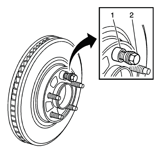
Fig. 26: Identifying Special Tool J 45101-100 & Lug Nut
8. Hold the rotor firmly in place against the hub/axle flange and install one of the CH-45101-100 Conical Brake Rotor Washers (1) and one lug nut (2) onto the upper-most wheel stud.
9. Continue to hold the rotor secure and tighten the lug nut firmly by hand.
10. Install the remaining CH-45101-100 Conical Brake Rotor Washers and lug nuts onto the wheel studs and tighten the nuts firmly by hand in a star-pattern.
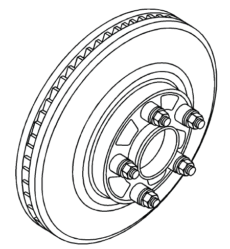
Fig. 27: Identifying All Special Tools J 45101-100s & Lug Nuts
11. Tighten the lug nuts in a star-pattern to specification, in order to properly secure the rotor. Refer to Tire and Wheel Removal and Installation.
12. Measure the assembled LRO of the brake rotor. Refer to Brake Rotor Assembled Lateral Runout Measurement.
13. If the brake rotor assembled LRO measurement still exceeds the maximum allowable specification, refer to Brake Rotor Assembled Lateral Runout Correction.
14. If the brake rotor assembled LRO measurement is within specification, install the brake caliper and depress the brake pedal several times to secure the rotor in place before removing the CH-45101-100 Conical Brake Rotor Washers and the lug nuts.
BRAKE ROTOR ASSEMBLED LATERAL RUNOUT CORRECTION - ON VEHICLE LATHE
NOTE: This procedure is not used in Europe.
Special Tools
- CH-45101-100 Conical Brake Rotor Washers
For equivalent regional tools, refer to Special Tools.
1. Ensure that the caliper and caliper bracket that are already being supported, are clear from contacting any rotating components, such as the brake rotor.
WARNING: Refer to Brake Dust Warning.
NOTE:
- Brake rotor thickness variation MUST be checked BEFORE checking for assembled lateral runout (LRO). Thickness variation exceeding the maximum acceptable level can cause brake pulsation. Refer to Brake Rotor Thickness Variation Measurement.
- Brake rotor assembled LRO exceeding the maximum allowable
specification can cause thickness variation to develop in the brake
rotor over time, usually between 4, 800-11, 300 km (3, 000-7, 000 mi).
Refer to Brake Rotor Assembled Lateral Runout Measurement.
2. Remove the CH-45101-100 Conical Brake Rotor Washers and the lug nuts that were installed during the assembled LRO measurement procedure and/or the indexing correction procedure.
3. Inspect the mounting surface of the hub/axle flange and the brake rotor to ensure that there are no foreign particles or debris remaining.
4. Set up the lathe, following the manufacturer's instructions.
5. Refinish the brake rotor, following the brake lathe manufacturer's instructions.
6. After each successive cut, inspect the brake rotor thickness. Refer to Brake Rotor Thickness Measurement.
7. If at any time the brake rotor exceeds the minimum allowable thickness after refinish specification, the brake rotor must be replaced. After replacing the rotor, proceed to step 10.
8. After refinishing the brake rotor, use the following procedure in order to obtain the desired non-directional finish:
- Follow the brake lathe manufacturer's recommended speed setting for applying a non-directional finish.
- Using moderate pressure, apply the non-directional finish:
- If the lathe is equipped with a non-directional finishing tool, apply the finish with 120-grit aluminum oxide sandpaper.
- If the lathe is not equipped with a non-directional finishing tool, apply the finish with a sanding block and 150-grit aluminum oxide sandpaper.
- After applying a non-directional finish, clean each friction surface of the brake rotor with denatured alcohol or an equivalent approved brake cleaner.
9. Remove the lathe from the vehicle.
10. Measure the assembled LRO of the brake rotor. Refer to Brake Rotor Assembled Lateral Runout Measurement.
11. If the brake rotor assembled LRO measurement still exceeds the maximum allowable specification, refer to Brake Rotor Assembled Lateral Runout Correction.
12. If the brake rotor assembled LRO is within specification, install the brake caliper and depress the brake pedal several times to secure the rotor in place before removing the CH-45101-100 Conical Brake Rotor Washers and the lug nuts.
BRAKE ROTOR REFINISHING
Special Tools
- CH-41013 Rotor Resurfacing Kit
- CH-42450-A Wheel Hub Resurfacing Kit
For equivalent regional tools, refer to Special Tools.
WARNING: Refer to Brake Dust Warning.
NOTE:
- The disc brake rotors do not require refinishing as part of routine
brake
system service. New disc brake rotors do not require refinishing.
Do not refinish disc brake rotors in an attempt to correct the following conditions:
- Brake system noise - squeal, growl, groan
- Uneven and/or premature disc brake pad wear
- Superficial or cosmetic corrosion/rust of the disc brake rotor friction surface
- Scoring of the disc brake rotor friction surface less than the maximum allowable specification
- Before refinishing a brake rotor, the rotor MUST first be checked for
adequate thickness to allow the rotor to be refinished and remain above
the minimum allowable thickness after refinish specification. Refer to
Brake Rotor Thickness Measurement.
Disc brake rotors should only be refinished if they have adequate thickness to be refinished and if one or more of the following conditions exist:
- Thickness variation in excess of the maximum allowable specification
- Excessive corrosion/rust and/or pitting
- Cracks and/or heat spots
- Excessive blueing discoloration
- Scoring of the disc brake rotor surface in excess of the maximum allowable specification
- Disc brake rotors may need to be refinished as part of the process for correcting brake rotor assembled lateral runout (LRO) that exceeds the maximum allowable specification.
NOTE: If the vehicle is equipped with cross-drilled rotors, use a lathe with positive rake tooling. This setup requires less cutting pressure, which will result in less vibration and a better surface finish. Also, use a vibration dampener when cutting. Otherwise, refinish according to the following instructions.
1. Using the CH-42450-A Wheel Hub Resurfacing Kit, thoroughly clean any rust or corrosion from the mating surface of the hub/axle flange.
NOTE: Whenever the brake rotor has been separated from the hub/axle flange, clean any rust or contaminants from the hub/axle flange and the brake rotor mating surfaces. Failure to do this may result in increased assembled lateral runout (LRO) of the brake rotor, which could lead to brake pulsation.
2. Using the CH-41013 Rotor Resurfacing Kit, thoroughly clean any rust or corrosion from the mating surface and mounting surface of the brake rotor.
3. Inspect the mating surfaces of the hub/axle flange and the rotor to ensure that there are no foreign particles or debris remaining.
4. Mount the brake rotor to the brake lathe according to the lathe manufacturer's instructions, ensuring that all mounting attachments and adapters are clean and free of debris.
5. Ensure that any vibration dampening attachments are securely in place.
6. With the brake lathe running, slowly bring in the cutting tools until they just contact the brake rotor friction surfaces.
7. Observe the witness mark on the brake rotor. If the witness mark extends approximately three-quarters or more of the way around the brake rotor friction surface on each side, the brake rotor is properly mounted to the lathe.
8. If the witness mark does not extend three-quarters or more of the way around the brake rotor, re-mount the rotor to the lathe.
9. Following the brake lathe manufacturer's instructions, refinish the brake rotor.
10. After each successive cut, inspect the brake rotor thickness. Refer to Brake Rotor Thickness Measurement.
11. If at any time the brake rotor exceeds the minimum allowable thickness after refinish specification, the brake rotor must be replaced.
12. After refinishing the brake rotor, use the following procedure in order to obtain the desired non-directional finish:
- Follow the brake lathe manufacturer's recommended speed setting for applying a non-directional finish.
- Using moderate pressure, apply the non-directional finish:
- If the lathe is equipped with a non-directional finishing tool, apply the finish with 120-grit aluminum oxide sandpaper.
- If the lathe is not equipped with a non-directional finishing tool, apply the finish with a sanding block and 150-grit aluminum oxide sandpaper.
- After applying a non-directional finish, clean each friction surface of the brake rotor with a solution of mild dish washing detergent and water or a GM approved brake cleaner and a clean shop towel to remove metal particles remaining from machining. Repeat the cleaning process if necessary to remove all metal particles.
NOTE: Thoroughly cleaning the brake rotor will prevent the possible transfer of finite metal dust left as a by-product of machining to the brake pad material during the burnishing process, thereby reducing the possibility for brake squeal or other brake noises to occur.
13. Remove the brake rotor from the brake lathe.
14. Measure the assembled LRO of the brake rotor to ensure optimum performance of the disc brakes. Refer to Brake Rotor Assembled Lateral Runout Measurement.
15. If the brake rotor assembled LRO measurement exceeds the specification, bring the LRO to within specifications. Refer to Brake Rotor Assembled Lateral Runout Correction.

