Buick Enclave: Cylinder Head Replacement
* PLEASE READ THIS FIRST *
NOTE: Examples used in this article are general in nature and do not necessarily relate to a specific engine or system. Illustrations and procedures have been chosen to guide mechanic through engine overhaul process. Descriptions of processes of cleaning, inspection, assembly and machine shop practice are included.
Always refer to appropriate engine overhaul article, if available, in the ENGINES section for complete overhaul procedures and specifications for the vehicle being repaired.
REMOVAL
NOTE: Examples used in this article are general in nature and do not necessarily relate to a specific engine or system. Illustrations and procedures have been chosen to guide mechanic through engine overhaul process. Descriptions of processes of cleaning, inspection, assembly and machine shop practice are included.
Always refer to appropriate engine overhaul article, if available, in the ENGINES section for complete overhaul procedures and specifications for the vehicle being repaired.
Remove intake and exhaust manifolds and valve cover. Cylinder head and camshaft carrier bolts (if equipped) should be removed only when engine is cold. On many aluminum cylinder heads, removal while hot will cause cylinder head warpage. Mark rocker arm or overhead cam components for location.
Remove rocker arm components or overhead cam components. Components must be installed in original location. Individual design rocker arms may utilize shafts, ball-type pedestal mounts or no rocker arms. For all design types, wire components together and identify according to corresponding valve. Remove cylinder head bolts. Note length and location. Some applications require cylinder head bolts be removed in proper sequence to prevent cylinder head damage. See Fig. 1. Remove cylinder head.
INSTALLATION
NOTE: Examples used in this article are general in nature and do not necessarily relate to a specific engine or system. Illustrations and procedures have been chosen to guide mechanic through engine overhaul process. Descriptions of processes of cleaning, inspection, assembly and machine shop practice are included.
Always refer to appropriate engine overhaul article, if available, in the ENGINES section for complete overhaul procedures and specifications for the vehicle being repaired.
Ensure all surfaces and head bolts are clean. Check that head bolt holes of cylinder block are clean and dry to prevent block damage when bolts are tightened. Clean threads with tap to ensure accurate bolt torque.
Install head gasket on cylinder block. Some manufacturers may recommend sealant be applied to head gasket prior to installation. Note that all holes are aligned. Some gasket applications may be marked so that certain area faces upward. Install cylinder head using care not to damage head gasket. Ensure cylinder head is fully seated on cylinder block.
Some applications require head bolts be coated with sealant prior to installation. This is done if head bolts are exposed to coolant passages. Some applications require head bolts be coated with light coat of engine oil.
Install head bolts. Head bolts should be tightened in proper steps and sequence to specification. See Fig. 1.
Install remaining components. Tighten all bolts to specification. Adjust valves if required. See VALVE ADJUSTMENT.
NOTE: Some manufacturers require that head bolts be retightened after specified amount of operation. This must be done to prevent head gasket failure.
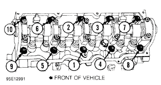
Fig. 1: Typical Cylinder Head Tightening or Loosening Sequence
VALVE ADJUSTMENT
NOTE: Examples used in this article are general in nature and do not necessarily relate to a specific engine or system. Illustrations and procedures have been chosen to guide mechanic through engine overhaul process. Descriptions of processes of cleaning, inspection, assembly and machine shop practice are included.
Always refer to appropriate engine overhaul article, if available, in the ENGINES section for complete overhaul procedures and specifications for the vehicle being repaired.
Engine specifications will indicate valve train clearance and temperature at which adjustment is to be made on most models. In most cases, adjustment will be made with a cold engine. In some cases, both a cold and a hot clearance will be given for maintenance convenience.
On some models, adjustment is not required. Rocker arms are tightened to specification and valve lash is automatically set. On some models with push rod actuated valve train, adjustment is made at push rod end of rocker arm while other models do not require adjustment.
Clearance will be checked between tip of rocker arm and tip of valve stem in proper sequence using a feeler gauge. Adjustment is made by rotating adjusting screw until proper clearance is obtained. Lock nut is then tightened. Engine will be rotated to obtain all valve adjustments to manufacturer's specifications.
Some models require hydraulic lifter to be bled down and clearance measured. Push rods of different length can be used to obtain proper clearance. Clearance will be checked between tip of rocker arm and tip of valve stem in proper sequence using a feeler gauge.
Overhead cam engines designed without rocker arms actuate valves directly on a cam follower. A hardened, removable disc is installed between the cam lobe and lifter. Clearance will be checked between cam heel and adjusting disc in proper sequence using a feeler gauge. Engine will be rotated to obtain all valve adjustments.
On overhead cam engines designed with rocker arms, adjustment is made at valve end of rocker arm. Ensure valve to be adjusted is riding on heel of cam on all engines. Clearance will be checked between tip of rocker arm and tip of valve stem in proper sequence using a feeler gauge. Adjustment is made by rotating adjusting screw until proper clearance is obtained. Lock nut is then tightened. Engine will be rotated to obtain all valve adjustments to manufacturer's specifications.

